“The only way to discover the limits of the possible is to go beyond them into the impossible.” – Arthur C. Clarke
Three months ago I started working at Snøhetta. On day one I was introduced to a project that a team of architects were already working on. The facade team on the project needed some assistance, and I started working on the outer skin.
I have never been this consumed by a project before. I have not done a single training session at my new company; not even a short presentation. I have done some external work, but at Snøhetta I have only worked on this project. It’s the coolest thing I have ever done. Here’s why:
The entire outer skin is a first class exercise in amazing visual programming and scripting for building information modeling and interoperability. Below follows a step-by-step recap of how the final result was produced. The summary excludes many of the mistakes I made, not out of pride but simply because the blog post would be too long.
When I started looking at how to model this facade in Revit, I didn’t know how to do it. It seemed impossible. I had some ideas, and fantastic people to help me, but the amount of components and data, rigorous placement and orientation rules, types and geometries, in addition to an insane amount of custom cut elements along multiple curved edges overwhelmed me with fear of failure. Today, looking back, I realize I had no reason to be afraid. Now I know what you can do with remarkable people around you, access to awesome customization and scripting tools and a little Revit skills.
People
The facade team line-up was composed of Peter French the dancing New Zealander; Luca Bargagli a tall and dark Italian facade engineer with a history in Paris and a perfect name for chanting; Rikard Jaucis who left just after I started, only to return for the post delivery party; and me. Peter had already worked with Rikard on the concept, and after a few short discussions we decided it would be beneficial to develop the entire facade in Revit, together with the rest of the building. Peter was the mastermind, Luca made it work, Rikard had been on the project since we started working on the competition, and I modeled the bastard. I am proud to say that apart from modeling family geometry in Revit, I did not manually place or manipulate a single family instance in the entire outer skin. It is also with great satisfaction I can state that neither Peter nor Luca had ever been in a Revit model before, and as the deadline approached both were making changes and synchronizing them in a large and complex worksharing environment. I’m impressed!


Base Geometry
The out skin geometry was developed in Rhino before I arrived, possibly by Rikard. The building shape deserves a blog post on it’s own, but in essence it’s a collection of 8 open surfaces. Two are vertical, three are straight but tilted, one is spherical and hence double curved, and the last bastard is a conical nightmare from the underworld.

Rhino Surface Facade Model
Having the base geometry in Rhino was perfect. I loved working with the surfaces in a true 3D CAD program, while creating relationships between geometries in Grasshopper. We could have done a better job at synchronizing coordinate systems at an early stage. For some reason, this is always a problem on projects. I don’t understand why; it’s really simple to set up Revit and Rhino projects to follow the same basic coordinate system rules, while maintaining different settings for export (with Survey Points in Revit and Export with Origin in Rhino, for instance). What I always do: use the same model rotation and keep all that shit as close to the same local origin as I possibly can.
Facade Design
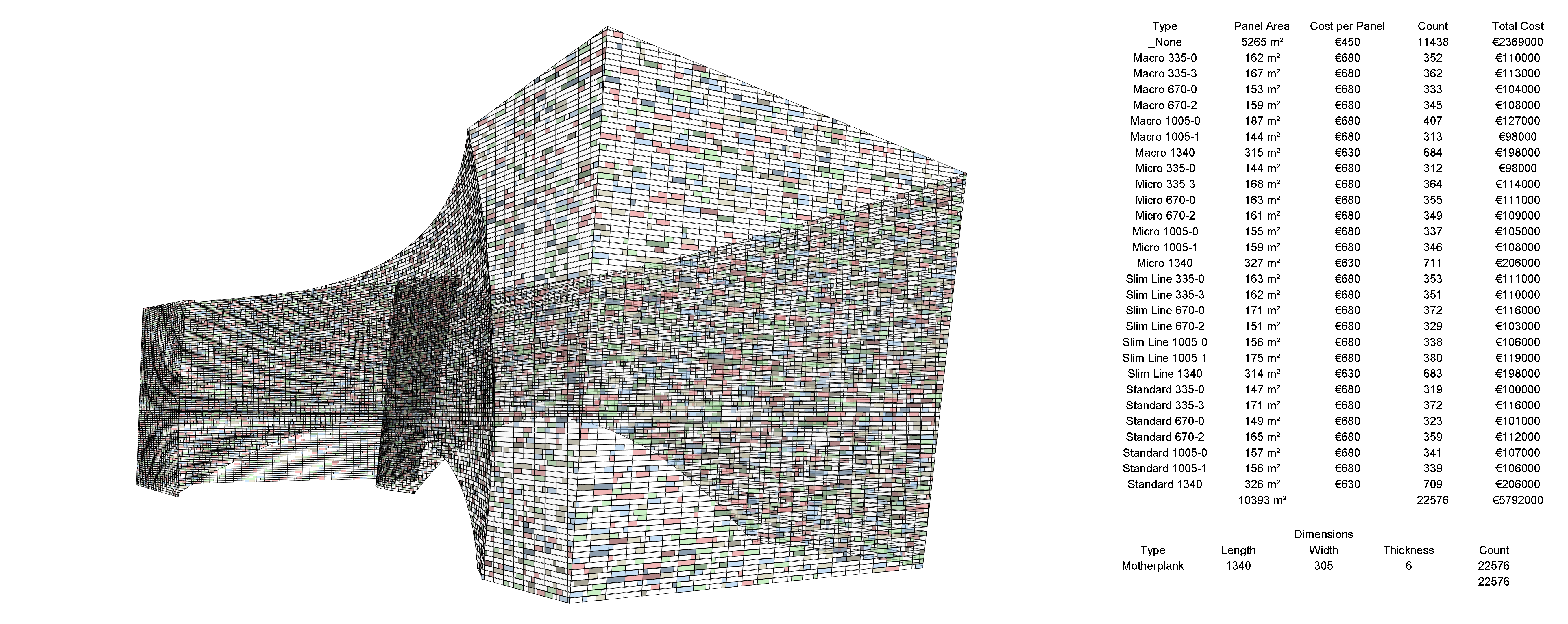
The facade was a double facade, with the inner skin a simple climate curtain wall. The outer skin was set up with two 6 mm thick glass plates (Motherplanks), 1.34 m wide and 305 mm high, glued together and fastened to the inner facade with steel T sections spanning between the floors. On 50 % of the Motherplanks we glued glass C channel profiles (Reglits) with 4 different surface treatments, 4 different lengths, placed at different sides of the Motherplanks and flipped. On 33 % of the non-flipped panels we sandblasted the backside of the Motherplanks where the Reglits were placed.
All beautifully randomized.
Because of the location of the inner facade mullions and T-sections, and the fact that all floors were perfectly horizontal (they usually are, aren’t they?), the panels needed to be placed at exact locations. That meant no standard UV Grid Tool could be used, and we had to create the facade grid ourselves. The only way we could do this was creating intersections between the facade surfaces, an array of horizontal Planes and vertical surfaces extruded from the vertical Mullion Grids. This only became apparent after we had failed with Surface Split for a few days. I was getting help for both Dimitar Venkov and Konrad Sobon to split the facade surfaces to multiple small surfaces, planarize all the surfaces and then extract the vertices for Adaptive Components placement. We had to discard that workflow for two reasons: Surface Split in both Dynamo (thanks Dimitar!) and Grasshopper (thanks Konrad!) is extremely slow. So is Adaptive Component placement and modification in Revit. Hence we decided to go a different way, and that turned out to be a wise choice.
Peter took charge one morning and called our Innsbruck office. Patrick Lüth and his colleague Andreas Glatzl answered the phone and we immediately began discussing working with panel center points instead. Panel center points naturally work well with one-point Generic Model Revit families. These families are also faster than other Revit elements (like Adaptive Components for instance) and easy to standardize with Type Parameters.

Andreas Glatzl (smart guy)
Andreas is pretty comfortable with geometry and lists in Grasshopper (heavy understatement there). With his scripting skills we were able to extract all panel center points and vectors, while also differentiating between the different facades and also edge and interior panels. We calculated the horizontal and vertical panel rotation angles between each panel normals and the Unit Y and Z Axis vectors in Grasshopper, and linked all these numbers along with the X, Y and Z coordinates of each panel’s center point to Dynamo with Mantis Shrimp.

Andreas Glatzl’s Grasshopper Script for extracting all panel center points and vectors

Panel Center Points and Vectors live linked to Dynamo with Mantis Shrimp
I suspect Konrad is getting tired of my praise, as it seems every time I present any work on Dynamo these days I hail his Mantis Shrimp Package. I don’t care. It’s pure awesome.
Revit Families
To be able to control the amount of panel types, we had to create a system of nesting families. The Motherplanks were created as simple Face Based Extrusions with Shared Length, Width, Height and Material Parameters. The Reglits were also Face Based, but Sweeps based on predefined Profile families, also with Width, Height, Length and Material Parameters. In addition we needed an empty family for panel instances with no Reglit. All families were constrained to the tilting Reference Line, and in addition the Reglits were constrained to an offset Reference Line for changing the placement sides with integers.

Panel Angle Parameter Changes animated with Dynanimator and GIMP 2
Both the Reglit and Motherplank families had a Flip Parameter (yes/no) that changed the panel facing orientation from convex to concave.
Last, the Sandblasting was added as a separate Face Based Family with a 0.8 mm thick sweep, inheriting the Length Parameters of the Reglits and the Height Parameters of the Motherplanks, with it’s own Material. We also linked it with a Visibility Parameter (yes/no) so that we could turn it on and off with Dynamo.

All 29 Types animated with Dynanimator for Dynamo and GIMP 2

Panel Facing Orientation animated with Dynanimator for Dynamo and GIMP 2
Panel Sandblasting animated with Dynanimator for Dynamo and GIMP 2
It’s a beautiful thing, and you can download a copy here: _panel (I often use underscore in the file names of the Revit Families I use in Dynamo. It makes them easier to locate.)
Dynamo
Once all the points and numbers (angles) found their way into Dynamo it was only a matter of copying and changing file paths to extract all the data we needed to place panels on all 8 facades. There is a Dynamo node that will horizontally rotate a family instance, and we used that to align all the panels in plan. The vertical rotation had to be done with an Instance Parameter, changing the tilt of a set of Reference Lines in the panel family, and thus tilting the Nested Families.
Mantis Shrimp linked 22576 points between Grasshopper and Dynamo, and eventually the latter placed and rotated an equal number of Revit families. That works when you do everything right the first time. I never do, and quickly found that I worked much more efficient when I built isolated facade surfaces, one at a time. That way the script ran much quicker, and I could do modifications to the scripts after generating each facade. Doing this with Dynamo 0.8.2 presented one huge problem: Element binding. When Dynamo creates a Revit Element (with a Revit Element ID), the node that performs that interaction will remember the ID of the element it created. This means that when we de-wire that node, Dynamo will delete the same element. This is designed for obvious reasons. The Dynamo Development Team wants Revit as synchronized with Dynamo as possible. So, when placing families on Facade 2 after using the same node for facade 1, we had to select all the generated families, Cut them to Clipboard (Ctrl+X), de-wire the placement node, Run Dynamo and finally using Paste to Same Place. When Dynamo runs and finds no Element ID’s (because they are deleted and copied to clipboard), the program will forget the elements. I have hopes that Dynamo comes with a Bake functionality on nodes that creates Revit Elements in the future.

Dynamo writing rotation and ID parameters to Revit Panel families

Dynamo Nodes for panel placement on one facade

Entire Dynamo panel placement definition
When placing the panel families, we placed a simple panel with no Reglits. After all panels were placed, we developed 4 Dynamo Scripts that in turn:
- Randomized 50 % of all panels to 28 different panel types. As mentioned above, these types varied between 4 glass treatments, 4 sizes, where 3 sizes had 2 different placements. The math goes like this: 4 materials * ((3 sizes * 2 sides) + 1 size) = 28 types.
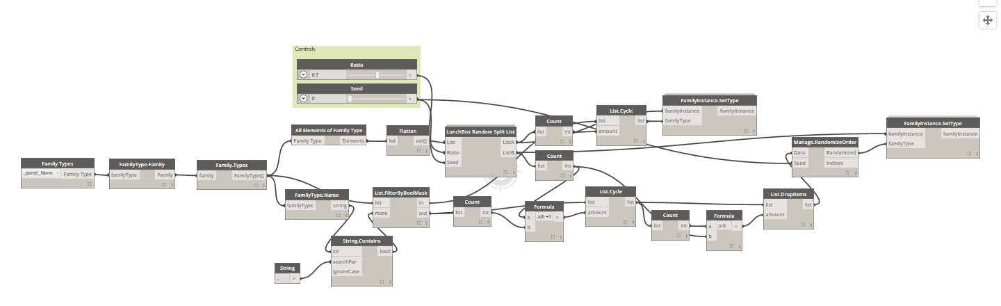
- Flipped the orientation (from concave to convex) of a randomized 50 % of the panels with Reglits.

- Added Sandblasting on the backside of the Motherplanks where there were Reglits, on 33 % of the concave (flipped) panels. All the randomization scripts used versions of Nathan Miller’s Lunchbox nodes.

- Cut (with Cut Geometry) all the Nested Families in all the Edge Panels with giant Closed Polysurfaces from Rhino, exported to SAT, imported and exploded in Generic Model families, Voided and loaded. This workflow used Julien Benoit’s Dynamo Package SteamNodes for cutting, and Jason Andersen’s BlackBox for collecting and organizing Nested Families.

That last procedure was dirty. Adding thousands of Cut Geometry relationships between Nested Families and imported and exploded SAT voids smells like trouble. It did work on this delivery, but it also did bloat the Revit Project file from about 30 to about 100 MB. It was awesome when we made it work, but I would not uncritically recommend the workflow on every design case.

Close up of one of the crazy corners
Complete Outer Skin Model in Revit

Facade Section

Complete Revit Model
I have done several presentations on visual scripting with Dynamo over the past years, and every time I do one, I talk about the existential pleasure of watching a computer work while you drink coffee and watch with a moist grin. The exercise above is the purest version of this phenomenon I have ever had. It was pure joy.
Sometimes we forget how lucky we are. When you get to overcome the seemingly impossible, with edge cutting technology that makes your heart beat on a complex, challenging and beautiful building project together with fantastic people, you should smile. Now, I do.

Leave a Comment
You must be logged in to post a comment.