Since we are getting close to a release of Revit 2017, I thought I would comment on some of the features of 2016 R2 before that release – of course all the R2 features will be included in Revit 2017.
Here is the list of features, derived from the Autodesk Knowledge Network (in purple), with my additions and comments (in black):
New in Revit 2016 R2
Platform – Multi-Disciplinary
Enhancements
Global parameters:
Global parameters bring the power of parametric
families into the project environment to better capture design intent.
- You can
create global parameters that are specific to a single project file but that
are not assigned to categories. Use global parameters to drive the value of a
dimension or a constraint, associate to an element instance property to drive
its value, or report the value of a dimension, so the value can be used in the
equations of other global parameters.
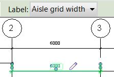
Global Parameters (GPs) can be applied in a similar way to the Family Editor:
- Apply to a dimension by selecting the dimension and changing its label (on the options toolbar); the label is not available for multi-segment dimansions.
- Once applied, the dimension has a small pencil symbol beside it.
- This means that two (or more) non-adjacent dimensions can have the same parameter applied to them
- Apply to the instance properties of an element by clicking on the tiny button that may appear to the right of a given property in the Instance Properties Palette
- Once applied, the button shows a tiny equals sign on it

This
promises to be a very powerful new feature, but it has many limitations at this
stage:
- They can
only be assigned to a very few system parameters on certain system family
categories (eg. To beams but not to floors) – and most likely not the ones you
want. - For external
families global parameters can only be assigned to user defined instance
parameters – not type parameters or system parameters. - You cannot assign them to array numbers
The Global Parameters dialog is accessed from the Manage tab. It has one long list of parameters, with no way to organise or group within the list apart from sorting alphabetically – so a naming convention will be vital, otherwise related parameters will be jumbled; there is a search capability, but it is fairly crude (it is actually a filter, not a search)

With great
power comes great responsibility. If
this feature is not well managed or controlled, it could make your models impossible to work with as they could end up with many hidden constraints and relationships. Changing parameter values can have dramatic effects on your model – like moving gridlines, so pinning and locking will be important.
- The ‘Reveal Constraints’ tool will show dimensions that have had global parameters assigned to them; but will not display global parameters assigned directly to instance parameters – the only indication of that is the tiny equals symbol in the instance properties dialog box.
- There is a ‘Show…’ button that will highlight elements or dimensions that have been constrained by GPs; once displayed on screen, you cannot navigate in a view with the GP dialog open. This does also work for elements that have GPs directly assigned to a property (unlike the Reveal Constraints tool)


- A Global parameter (GP) can be used in formulas for other parameters; however, if a GP is deleted, then any formulas using that GP will also be cleared, without warning – as per in the family editor. In the family editor that would affect only that family, but with Global Parameters it would affect the whole project.
- You can add tooltips to Global Parameters but they only show up in the dialog box, which is of limited usefulness. It would be better if they showed in-canvas in the model. However, they should always be used as a record of what each parameter is for.
Performance:
Occlusion culling:
- To improve performance and reduce the amount of time
required to open views, the Graphics tab of the Options dialog offers a new
setting: Draw visible elements only. This setting is enabled by default.
Performance improvements are most noticeable when opening or navigating around
3D views that contain many obscured elements, because Revit does not even try to draw the hidden elements.
Export to DWF/DWFx:
To significantly reduce processing time when
exporting views/sheets to multiple DWF or DWFx files, the software now uses multiple
“RevitWorker” processes.
Color fills:
To improve performance, color fills are completed as a
background process so you can continue working in the model while the views
update.
Background processes:
The status bar now displays a list of the processes, such as
color fills, running in the background
UI tweaks
Object Styles:
In the Object Styles dialog, you can now select and
delete multiple subcategories at once. Press and hold the Ctrl key or Shift key
while selecting subcategories, and then click Delete.
Family Types Dialog
The Family Types dialog box has been changed to use icons instead of written commands – they are tiny icons but at least they are consistent with some other newer dialogs.
Cancel print/export:
When you print or export multiple views and
sheets, the <Cancel> button allows you to to cancel the entire batch operation
(all selected views and sheets). In earlier releases, the Cancel button allowed
you to cancel only one view or sheet at a time, which was very tedious and
time-consuming. This will be a life-saver when you started a batch print just before a deadline, and realised you made a mistake!
Family Editor – Visibility Preview:
In the Family Editor, you can view
improved representations of family geometry to see how it might look in the
project with respect to:

- visibility
parameter settings

Create, test
and edit the geometry of a family without having to repeatedly load it into a
project to see what it looks like.
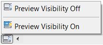
-
On the View Control Bar, click <Preview
Visibility: On>. - In plan views,
you can click <Preview Visibility: Not Cut> to see the family represented as a
projection. - Note: To exit the Preview Visibility mode,
on the View Control Bar, click <Preview Visibility: Off)>
When you preview
the family geometry, the drawing area of the Family Editor is highlighted with
a yellow border labelled Preview Visibility. The overlapping 2D and 3D
geometries are hidden, where the visibility settings of elements match those of the view.
Obviously you need to change the actual view settings in the family editor to see the result.
This should take a lot of guesswork out of the equation, and be a good time-saver.
Family Editor – Filter voids and solids:
You can specifically isolate
void and solid geometry when using the Filter tool in the Family Editor.
The filter list now shows solid elements by their subcategory, or parent category if unassigned;
Voids are listed by parent category, with (Void) as a suffix

The properties dialog also lists by the same category subdivision

Revisions:
Additional information is available for revisions to make it easier to see
exactly how the revision number will be generated, and to select revisions to
include in a revision schedule.
Sheet Issues/Revisions dialog:
When Numbering is set to Per Project,
a new Revision Number column displays the actual revision number that will be
generated based on the Sequence, Numbering scheme, and Numbering options. This
column does not display if Numbering is set to Per Sheet.
Revisions on Sheet dialog:
A Revision column now displays the revision
sequence information along with the revision description. A new Date column
displays the revision date.
Revit links – Positioning:
Improved workflow when using Revit
links in the host model if you are not using Shared Coordinates:
positioning option, Auto – Project Base Point to Project Base Point, is
available when inserting Revit
links. This option positions the linked file using the model’s Project Base
Point as the insertion point, and aligns it to the Project Base Point in the
host model. The position does not update
if the Project Base Point changes

Two options
are available to reposition a Revit link after it has been inserted: Reposition to Project Base Point, and
Reposition to Internal Origin.
This is available as a right-click command when you select a link.
Wow, this little gem could be a life-saver, when someone accidentally moves a linked file, you can just move it back – providing it was originally located either by Base Point or Origin.

However, I would still recommend pinning all your links immediately after first placing them.
Revit links – Unloading:
When you are working in a local copy of a
workshared model, the Unload command offers 2 options:
- Unload
> For all users: The Revit
link is unloaded for all users in the model (existing behavior). On the Manage Links dialog, this is just labelled as “Unload” - Unload
> For me: The Revit
link is unloaded for the current user only. This command works like a permanent
override and remains set for the current user for that RVT link until it is
cleared. This option allows you to unload and keep Revit
links unloaded for portions of the model you aren’t working on without
affecting other team members. Unloading Revit
links may also increase performance and reduce memory usage.
These options are available when selecting a link in the Manage Links dialog. They are also available by right-clicking on Revit links in the Project Browser

The setting
is stored in the central model, per user for each Revit link.
- To reverse the unloading of the link per user, select the link (in Manage Links) then click on “Clear my override” or right-click the link name in the Project Browser, and click Unload > Clear my
override – the load status will then revert to how it is set for all users (in the central file). The ‘Clear my override’ button is only available if the selected link has been unloaded for a user. - If the Revit link has been globally unloaded with the Unload > For
all users command, the Revit link is still unloaded for the current user.
This looks like being a good time-saver. Many BIM managers try to get their staff to use worksets to achieve a similar result (unload per user), but that is quite confusing to many people and it often does not happen. Hopefully this new feature will be more understandable to the average Revit user, and it will be implemented. The only thing this new feature cannot do is to pre-select which links to load when opening a file (which is easy to do with worksets).
Worksharing:
When you are opening a workshared model and you select the ‘Detach from Central‘
option, the default name of the open model is now the original model name with
“_detached” appended (instead of a blank file name). When saving the
model, you can specify a name or use the default.
View Properties
View range:
The View Range dialog has been improved to provide
visual descriptions of view range terminology, making it easier for you to set
the view range. Click on the <<
Show button to see a graphic description

If you go to a reflected ceiling plan and look at the view range dialog, you
might expect the description diagram to be a little different – well, it is not! It is the same one that applies to plan
views. This is the one situation where
the average Revit user gets confused, and might need help, but does not get it –
in fact it is a hindrance!
Underlay:
The Underlay properties have been improved to more clearly define what they do.
A new
grouping in the Properties palette ‘Underlay’, contains the properties used to
set an underlay range. The old ‘Underlay’ parameter is renamed to ‘Range: Base Level’.
A new read-only parameter Range: Top Level displays the next level above the
Range: Base Level. The options for Underlay Orientation are changed from
Reflected Ceiling Plan to Look Up, and from Plan to Look Down.
 |
| Plan Underlay |
 |
| RCP Underlay |
properties – it does not give you any more control than you had before. When you set an underlay level, the top level
is automatically set for you as the level above the one you selected as base
level – you have no choice.
Interestingly, if you then add another intermediate level to your model
(between the base and top levels) your underlay settings for a given view do
not change, thus allowing your underlay to extend across two levels – maybe you
could use that to your advantage somehow?
The underlay is looking down (or up) at a 3D model between the base and
top levels – it is not cutting a horizontal section like the actual plan view
does. That is why underlays don’t look
like plan views from another level – instead you just see chunks of the model
in a rather uncontrolled manner, hence they are very unpredictable, and seldom
useful in a plotted drawing.
New views no
longer have an underlay set automatically – it is set to “None” by default
Hurrah! It is worth upgrading to R2 just
for that.
Filters dialog:
The Filters dialog has been improved to make it easier
to find specific filters in the list. Filters are listed alphabetically and
sorted in a tree structure with headings for rule-based and selection-based
filters.
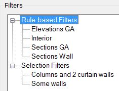
Finally we have alphabetic lists for filters!
Why did it take so long?
Reference plane names:
You can name reference planes directly in the
drawing area. In the drawing area, click on the text label for a reference
plane to define or change its name.
Many users do not bother to name reference planes even if really important. Maybe this will help BIM managers persuade them to do so as it has been made marginally easier
Architectural
Enhancements
Perspective views:
Copy and Paste are now available in
perspective views.
- Modify panel
> (Copy) - Clipboard
panel
> Paste drop-down > (Paste from Clipboard), and any available tool
from the drop-down
Personally I think this is a waste of development resources, as I would never do a precise modeling exercise like pasting model elements in a perspective view. I guess it is just to keep the Sketchup naysayers quiet!
Spot slope:
You can now place a spot slope annotation in a linked
model.
I have not tried this but I assume it means that you can place a spot slope annotation on an element in a linked
model, but the annotation remains in your active model (rather than inside a linked model)?
Wall joins:
- When placing
walls, you can allow or disallow wall joins with the Join Status option – before you place the walls.

Could be useful if you are placing a whole lot of curtain walls for example.
- You can
select multiple wall joins and change the configuration of all selected joins
to Butt, Miter, or Square Off:
Use the ‘Join Walls’ tool

Select multiple wall joins, and change the join type or allow/disallow joins using the Options toolbar – I don’t imagine wanting to change the join type on multiple walls (as they are normally one off operations), but the multiple allow/disallow joins should be very useful. The workflow is not very intuitive (invoke the command then select multiple joins by dragging across), but I’m sure we’ll get used to that.
Both these features should make life easier
Railings:
When you edit the Type properties of a railing, you can now use the Preview
pane of the dialog to view your changes.


- The preview shows a fixed segment length of about 1500mm (that is 5 feet to the imperialists), so if your baluster repeat distance is quite large, it won’t make a lot of sense.
- You have to click ‘Apply’ to see the updated preview, which could be painfully slow if you have lots of railings in the model as they’d need to be updated before you see the preview!
Autodesk Raytracer rendering:
Define a custom render quality to specify
light and material accuracy, and render duration options.
Energy Analysis:
- Advanced
thermal zoning: Revit
now offers automatic thermal zoning that uses advanced algorithms, resulting in
more accurate energy simulations without additional modeling. - On the
ribbon, the Enable
Energy Model tool has been renamed to Create
Energy Model. - The accuracy
and appearance of analytical surfaces has been improved. Edges are less
pixilated, and surfaces are more accurate and less faceted. As a result, the
energy analytical model is more accurate, looks better, and generates a smaller
XML file.
Mechanical, Electrical, and Plumbing Engineering Enhancements
Fabrication:
The following changes help to improve workflow and productivity for fabrication detailing tasks.
- Insert part: You can place a tee, valve, damper, or in-line equipment into a straight duct or pipe segment.
- Connect as tap: You can connect a duct fabrication part fitting to a rectangular main using the same behavior as a tap.
- Rotation tools: To improve ease of use, you can use ribbon commands and in-canvas controls to rotate fabrication parts.
- Show service: To make it easier to select a service in the MEP Fabrication Parts palette, Show Service sets the palette to the selected model
element’s service.
Electrical settings:
You can specify a default rating to use for creating
circuits in a model.
Assigning a distribution system:
If there is only one distribution system
applicable to an equipment instance, the distribution system is now assigned
automatically.
Structural
Um, er,
nothing to report! I bet the structural
engineers won’t be in a hurry with this upgrade
Links
Steve Stafford has commented on a number of the Revit 2016 R2 features (documented or undocumented changes he just found) on Revit OpEd:
Autodesk Knowledge Network Link Revit 2016 R2
What’s New in Revit 2017 – coming soon . . . . . .
Leave a Comment
You must be logged in to post a comment.